
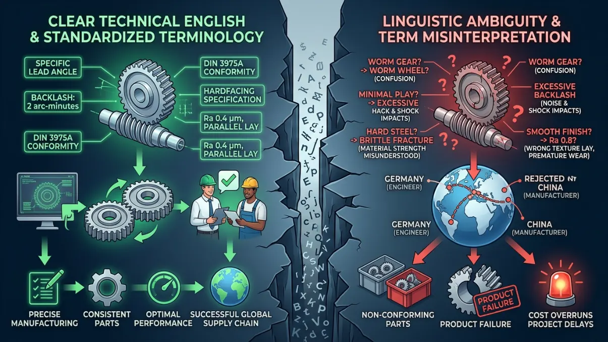
In today’s global manufacturing landscape, a worm gear technical drawing authored in English by an engineer in Germany can be misinterpreted by a worm gear manufacturer in China, leading to non-conforming parts. This communication gap, rooted in imprecise technical English vocabulary, is a common source of project delays, cost overruns, and product failures. A subtle terminology error, such as confusing “tolerance” with “allowance,” can render parts un-assemblable or prone to premature wear.
The core issue is that technical English is not merely a variant of everyday language; it is a precise, unambiguous symbolic system. While many engineers possess strong general English skills, they often lack training in the standardized terminology for specific mechanical components like worm gears. Relying on translation software or generic language courses fails to address the nuanced yet critical semantic differences in engineering drawings and specifications. This article will demystify three pivotal term groups in worm gear design to ensure manufacturing consistency across the global supply chain.

Why Is Precise Terminology Critical in Worm Gear Design and Manufacturing?
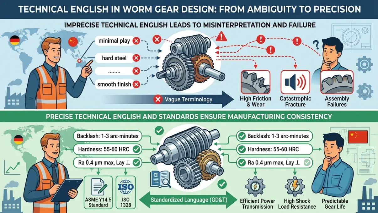
Clear technical communication is the bedrock of precision manufacturing, and its importance is magnified in complex components like worm gears. The unique right angle worm drive and high-torque characteristics of a worm gear set amplify the consequences of ambiguous terms. A misunderstood “lead angle” or “backlash” specification can directly lead to inefficient power transmission, excessive noise, or outright failure. Adopting standardized languages like Geometric Dimensioning and Tolerancing (GD&T) per the ASME Y14.5 standard is not optional; it is essential for ensuring that design intent is perfectly translated into a physical part, regardless of where it is produced.
- The High Cost of Linguistic Ambiguity in Engineering: Every term in a technical specification carries the weight of functional and financial implications. In worm gear manufacturing, a requirement like “minimal play” is subjective and open to interpretation, whereas a callout for “backlash not exceeding 3 arc-minutes” is a quantifiable, verifiable target. This precision directly dictates the manufacturing processes, inspection methods, and ultimately, the performance and cost of the final assembly. Vague language forces the manufacturer to make assumptions, increasing the risk of producing parts that are either over-engineered and expensive or under-specified and unreliable.
- Standards as the Universal Engineering Language: Referencing established international standards is the most effective strategy to eliminate ambiguity. When a drawing specifies that a gear tooth profile must conform to “DIN 3975A” or that a material must meet “SAE 8620,” it invokes a complete, pre-defined set of specifications understood globally. This practice moves communication from subjective description to objective reference, ensuring all stakeholders — designers, custom worm gears suppliers, and quality inspectors — are aligned to the same rigorous benchmarks without lengthy explanatory notes.
- Building a Shared Lexicon with Your Supply Chain: Precision is a partnership. Proactively developing a shared technical glossary with your manufacturing partners is a strategic investment. This glossary should define critical application-specific terms, such as what constitutes “smooth operation” or “high shock load” in your context. Formalizing this understanding, often through a First Article Inspection (FAI) report that includes agreed-upon measurement protocols, transforms technical English from a potential barrier into a powerful tool for quality assurance and collaborative problem-solving.
How Does Misunderstanding “Backlash” Lead to Assembly Failures and Noise Issues?
Backlash, the essential clearance between mating gear teeth, is often misinterpreted. Confusing it with general clearance can cause a “bound mesh” (gears too tight), leading to overheating and failure, while excessive backlash causes inaccuracy and vibration. Correct specification — defining it as the angular movement of the output gear when the input is fixed — is critical. A competent worm gear manufacturer specifies a permissible range (e.g., 1-3 arc-minutes) based on the application’s precision needs, preventing these costly failures.
1. Defining Backlash: More Than Just “Loose Fit”
Technically, gear backlash is the distance through which a gear can be rotated without moving its mating gear. It is a functional requirement, not a manufacturing defect. In a worm gear set, it must be carefully calculated considering factors like thermal expansion, lubricant film thickness, and tooth deflection under load. A specification must clearly state whether it refers to circumferential backlash, angular backlash, or linear backlash, and define the measurement method, as each yields a different value. Without this clarity, verification becomes subjective, and consistency is lost.
2. The Consequences of Improper Backlash Specification
Insufficient backlash creates a preloaded mesh, drastically increasing friction and operating temperature. This can degrade the lubricant, accelerate wear on the gear tooth flanks, and ultimately lead to scoring and pitting. The system will draw more power, operate inefficiently, and generate significant noise. On the other hand, excessive backlash manifests as audible clunking during start-stop or direction reversal, causing impact stresses that can fracture teeth. It also destroys precision in indexing or positioning applications, making it unacceptable for robotics or automation.
3. Specifying Backlash for Application Success
The correct backlash value is application-dependent. A high-torque, slow-speed lifting application may tolerate slightly more backlash for robustness, while a servo-driven positioning system requires near-zero backlash for accuracy. The specification must be explicit: “Backlash, measured at the output shaft with the worm fixed, shall be 2 ±1 arc-minutes under no-load conditions at 20°C.” This level of detail, including measurement conditions, provides an unambiguous target for manufacturing and final inspection, ensuring the assembled unit performs as intended.
How Adults Learn Best: Why Education Needs a Different Approach
What Are the Consequences of Confusing “Hardness” with “Strength” in Material Specifications?
Material specification errors are among the costliest in manufacturing. Using “hardness” and “strength” interchangeably is a critical mistake. Hardness (e.g., HRC, HB) is a material’s resistance to surface indentation or scratching. Tensile strength is the maximum stress a material can withstand while being stretched before failing. Yield strength is the stress at which it begins to deform plastically. Specifying only “hard steel for worm” could lead a supplier to select a very hard, high-carbon steel that is brittle and susceptible to catastrophic fracture under the impact loads common in starting and stopping, rather than a tough, alloy steel like SAE 4140 that can withstand shock.
1. The Distinct Roles of Hardness, Strength, and Toughness
In gear design, these properties serve different masters. Surface hardness is paramount for wear resistance; the worm’s threads must be hard to resist abrasion. Core strength (yield and tensile) is critical for load-bearing capacity, preventing bending or permanent deformation under high torque. Material toughness — the ability to absorb energy without fracturing — is vital for surviving shock loads. A specification that calls for “SAE 4340, oil-quenched and tempered to 280-320 HB, with induction-hardened flanks to 55-60 HRC min case depth 0.5mm” precisely communicates the need for a tough core with a wear-resistant surface.
2. The System Approach to Worm and Wheel Material Selection
Worm gear design requires a tribological system view. The materials for the worm and wheel are not chosen in isolation but as a coupled pair. The classic combination is a hardened steel worm and a softer bronze wheel. The hardness differential ensures wear is concentrated on the more replaceable gear. Specifying the exact bronze alloy (e.g., ZCuSn10P1 for general use, ZCuAl10Fe3 for high shock) is as important as specifying the steel. This paired material science ensures controlled wear, efficient heat dissipation, and proper lubrication film formation.
3. From Specification to Verified Property
A proper material callout must be verifiable. It should state the material standard (e.g., ASTM A29), the grade (e.g., 8620), the heat treatment process (e.g., carburizing), and the resultant properties (e.g., surface hardness, case depth, core hardness). This allows the manufacturer to source correctly and enables the quality team to perform validation tests like hardness traverses and metallographic analysis. Relying on generic terms like “high-strength steel” delegates the material choice to the supplier, introducing significant performance risk.
Workplace English Communication Skills Every Professional Needs
How Can Ambiguity in “Surface Finish” Callouts Result in Premature Wear?
Surface finish, often loosely called “smoothness,” is a multi-dimensional characteristic that profoundly affects the performance, wear, and lubrication regime of mating gears. Simply specifying a numeric “Ra” (Arithmetic Average Roughness) value, like “Ra 0.8,” is insufficient and can lead to premature failure. Ra is an average height descriptor; two surfaces with the same Ra can have entirely different texture patterns — one directional (lay) and one isotropic — which drastically alter lubricant retention and wear-in behavior. For a worm gear set, the directionality of the grinding marks on the worm thread must be controlled relative to the direction of sliding motion.
1. Beyond Ra: The Complete Picture of Surface Texture
A comprehensive surface finish callout should specify multiple parameters. Rz (Mean Roughness Depth) can be more representative of peak-to-valley height than Ra. The lay symbol (e.g., = for parallel, ⊥ for perpendicular, X for crosshatched) on an engineering drawing dictates the orientation of the machining marks relative to the contact motion. For a worm thread, a lay parallel to the direction of sliding is often desirable to promote hydrodynamic lubrication. Additionally, specifying the sampling length and evaluation length for measurement ensures consistent inspection results between the manufacturer and the customer.
2. The Direct Link Between Finish, Friction, and Failure Modes
The surface roughness profile directly dictates the coefficient of friction and the type of wear. A rough surface operates in a boundary lubrication regime where asperities contact, leading to high friction and wear. A properly finished surface supports elastohydrodynamic lubrication (EHL), where a thin, high-pressure film separates the surfaces. An incorrect finish can cause scuffing (adhesive wear), micropitting (fatigue wear), or excessive running-in wear. Specifying the correct finish, therefore, is a direct method of controlling the tribological system and ensuring predictable gear life.
3. Specifying for Function, Not Just a Number
The finish requirement should be derived from the function. For the flanks of worm gear teeth, a fine finish (e.g., Ra 0.4) is needed for smooth rolling and sliding contact. For a shaft bearing journal, a different finish and lay pattern might be optimal. The callout should be as specific as: “Tooth flanks: Ra 0.4 µm max, Rz 2.0 µm max, lay parallel to worm axis.” This functional approach ensures the manufacturing process (e.g., grinding with a specific wheel dressing technique) is selected to achieve the required performance characteristic, not just an arbitrary number on a chart.
What Resources Can Engineers Use to Standardize Technical English in Global Teams?
Combating terminology ambiguity requires proactive measures and the use of authoritative resources. The first and most powerful resource is the body of international standards themselves. Incorporating by reference standards like ISO 1328 for gears, ASME Y14.5 for GD&T, and SAE J standards for materials into contractual documents provides an indisputable technical lexicon. Creating and maintaining a project-specific glossary is equally vital. This living document should define all critical terms, acronyms, and acceptable abbreviations, and be shared with all suppliers and team members.
Leveraging International Standards as the Definitive Source: Formal standards are the most reliable resource for term definitions. When a contract states that a part must be “manufactured in accordance with ISO 1328-1:2013, Accuracy Class 6,” it invokes a complete set of definitions for errors like profile deviation, pitch error, and runout. Engineers should habitually refer to the “Terms and Definitions” section of relevant standards. Building a personal or team library of key standards, and training on how to apply them, is a foundational step toward standardizing communication and ensuring that everyone interprets “quality” and “precision” through the same lens.
Developing and Enforcing a Project Glossary: A dynamic project glossary goes beyond a simple word list. It should contain terms, their precise definitions sourced from standards where possible, approved abbreviations, and even examples of correct usage. For instance, it would clarify: “Backlash: As defined in AGMA 1012-F90, the amount of clearance between mated gear teeth. On this project, it is measured as circumferential backlash at the worm wheel pitch circle under no-load conditions. Do not use ‘play’ or ‘lashing’ as substitutes.” This document should be controlled, versioned, and accessible to all stakeholders, forming the basis for all technical communications and drawing notes.
Cultivating a Culture of Clarification and Verification: Ultimately, the best resource is a proactive engineering culture. This culture encourages asking for clarification — “When you say ‘high efficiency,’ can we define that as a minimum of 88% at the rated load?” — and mandates verification. This includes practices like model-based definition (MBD) where 3D CAD models contain embedded product and manufacturing information (PMI), reducing reliance on ambiguous text notes. It also means conducting design reviews with manufacturing partners early in the process to align on terminology and feasibility, preventing costly misunderstandings downstream.
H2: How Does a Certified Manufacturing Partner Bridge the Language Gap to Ensure Precision?
The ultimate safeguard is partnering with a manufacturer certified to standards like ISO 9001 and IATF 16949. This framework mandates rigorous contract review, forcing a technical dialogue to transform subjective terms into quantifiable metrics. A capable partner acts as an engineering extension, clarifying intent and preventing errors through systematic validation. This process ensures every specification, from material to finish, is executed as intended. It is the critical defense delivering the reliability demanded by high performance automotive gear manufacturers.
1. Quality Systems as Communication Safeguards
Certified quality management systems like ISO 9001 are not just about inspecting finished parts; they are about preventing errors. A core clause requires that “the organization shall ensure that… the requirements for the products and services are defined.” In practice, this means a competent certified manufacturer will have a formal order review checklist. When they receive a drawing calling for a “hardened worm,” their system flags it as ambiguous. They will then issue a Request for Information (RFI) to clarify: “Please specify material grade, hardness scale (HRC/HB), hardness value, and case depth.” This institutionalized questioning closes the communication loop.
2. The Technical Alignment Process: From Words to Numbers
Beyond system mandates, a true partner engages in technical collaboration. For a high-torque worm gear application, they won’t just accept the term “high torque.” They will initiate a discussion to define the load profile: Is it continuous or cyclical? Are there shock loads? What is the required service factor? This dialogue transforms a vague requirement into a detailed performance specification that can be designed and tested against. This process is especially valuable for custom applications, where off-the-shelf assumptions do not apply, and clear, mutual understanding is the foundation of success.
3. The Partnership Advantage: Shared Risk, Shared Success
Choosing a partner with deep application expertise and robust processes changes the relationship from transactional to collaborative. They share the risk of miscommunication. Their engineers, fluent in both technical English and the practical realities of manufacturing, act as translators and validators. They ensure that a callout for a specific surface roughness is achievable and appropriate for the material, or that a specified gear tolerance is measurable and fit for purpose. This partnership, built on clarified intent and verified capability, is the most effective strategy for navigating the complexities of global precision manufacturing.
Conclusion
In precision fields like worm gear manufacturing, the exact use of technical English is critical — misinterpreting terms like backlash or surface finish directly leads to failure and loss. Success hinges on mastering precise terminology, rigorously applying international standards, and fostering a culture of meticulous specification. Partnering with a certified manufacturer bridges the communication gap, as their structured systems ensure every requirement is validated and executed. This dual strategy transforms global collaboration into a reliable driver of innovation and quality.
FAQs
Q1: What’s the difference between “worm gear” and “worm wheel” in technical drawings?
A: The “worm” is the screw-like driving component. The “worm wheel” (or “gear”) is the driven gear that meshes with it. Confusing these terms can lead to incorrect procurement or assembly. Always specify both separately in your Bill of Materials (BOM) and drawings to eliminate supplier ambiguity and ensure correct manufacturing.
Q2: How should I specify the “efficiency” of a worm gear set in English to avoid performance disputes?
A: Avoid vague terms like “high efficiency.” Instead, specify a quantifiable target under defined conditions, e.g., “Minimum 85% efficiency at a rated input speed of 1000 RPM and output torque of 50 Nm.” Referencing a test standard (e.g., AGMA) provides a clear, verifiable basis for acceptance with your manufacturer.
Q3: Is “self-locking” a guaranteed feature of all worm gears? How should I communicate this requirement?
A: No, self-locking depends on the lead angle and friction. State the requirement precisely: “The set must be self-locking, defined as the output shaft being unable to back-drive the input worm when a static torque of [X Nm] is applied.” This testable definition ensures the feature is designed and validated correctly.
Q4: What English terms are critical when discussing heat treatment for worm gears?
A: Specify the process (e.g., “case hardening”), the material standard (e.g., “per SAE 8620”), and the resultant properties (e.g., “surface hardness 58-62 HRC, case depth 0.5-0.8 mm”). Avoid just “hardened.” This precise language ensures the thermal processing meets your fatigue and wear life expectations.
Q5: Can poor English in my CAD file notes (like “chamfer edges”) cause manufacturing issues?
A: Absolutely. “Chamfer” is a specific angled edge break. If you mean a rounded edge, the term is “fillet” or “radius.” Misusing “chamfer” could create stress concentrators. Use standardized GD&T symbols on drawings and provide detailed documentation alongside 3D files to eliminate ambiguity for all suppliers, including high performance automotive gear manufacturers.
Author Bio
The insights in this article are provided by the engineering team at LS Manufacturing, a precision manufacturing specialist dedicated to helping global clients transform complex designs into flawless reality. The team leverages deep expertise in advanced manufacturing processes and a commitment to clear, precise communication to ensure project success from specification to delivered part.